Guide to Names and Functions of Components

- Do not obstruct the machine's vents. Doing so risks fire caused by overheated internal components.
Region A and Region B symbols
 (mainly Europe and Asia), (mainly Europe), or (mainly Asia)
 (mainly North America)
Differences in the functions of Region A and Region B models are indicated by two symbols.
Read the information indicated by the symbol that corresponds to the region of the model you are using.
For details about which symbol corresponds to the model you are using, see "Model-Specific Information".
Front and Left View
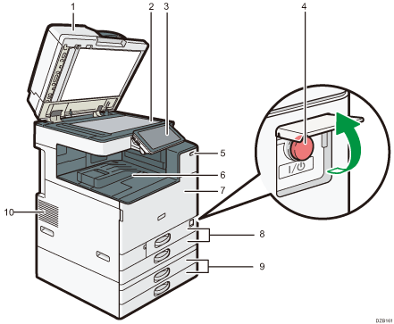
Exposure glass cover/Auto Document Feeder (ADF)
Lower the cover over originals placed on the exposure glass.
If you load a stack of originals in the ADF, the ADF will automatically feed the originals one by one.
Exposure glass
Place originals facedown here.
Control panel
Main power switch
To turn the power on and off, open the cover of the main power switch and press the main power switch.
Human detection sensor
Detects a person approaching the machine.
Recovering from Sleep Mode When a Person Approaches the Machine
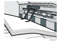
Internal tray 1
Copied/printed paper and received fax pages are delivered here. And the paper is output under the paper holder attached inside the internal tray.
Front cover
Open to access the inside of the machine.
Paper trays (Trays 1, 2)
Standard paper trays. Load paper here.
Lower paper trays (Trays 3, 4)
Optional paper trays. Load paper here.
Vents
Holes for ventilating the inside the machine to prevent the internal components from overheating.
After large-volume printing, the ventilation fan may continue to work to lower the temperature inside the machine.

Note the following when using the paper holder of the internal tray:
Once you have drawn out the output sheet on the top of the internal tray, do not push the sheet back under the paper holder. The paper holder does not work on the output sheet properly and may cause a paper jam.
Front and Right View
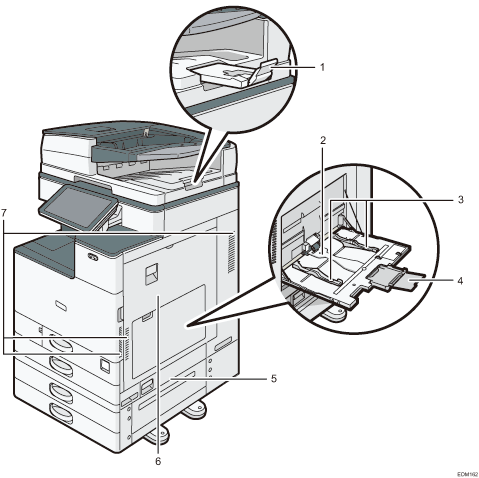
ADF tray extender
Pull this extender out to prevent originals larger than B4 or 81/2 × 14 size from falling.
Bypass Tray
Use the tray to copy or print on OHP transparencies, adhesive labels, and paper that cannot be loaded in the paper trays.
Paper guides
When loading paper in the bypass tray, align the paper guides with the edges of the paper.
Extender
Pull this extender out when loading paper larger than A4
 , 81/2 × 11.
Lower right cover
Open this cover to remove jammed paper.
Right cover
Open this cover to remove jammed paper.
Vents
Holes for ventilating the inside the machine to prevent the internal components from overheat.
After large-volume printing, the ventilation fan may continue to work to lower the temperature inside the machine.
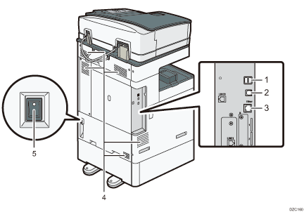
Rear and Left View (mainly Europe) (mainly North America)
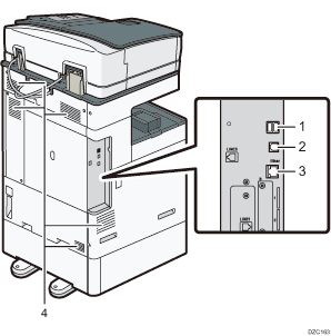
USB2.0 Interface Type A
Use the port to connect the IC card authentication device.
USB2.0 Interface Type B
Use the port to connect the machine and the computer with the USB cable.
Ethernet interface
Used the port to connect the machine to the network or to use the remote management service (RICOH @Remote) over the Internet.
Vents
Holes for ventilating the inside the machine to prevent the internal components from overheat.
After large-volume printing, the ventilation fan may continue to work to lower the temperature inside the machine.
Rear and Left View (mainly Asia)
USB2.0 Interface Type A
Use the port to connect the IC card authentication device.
USB2.0 Interface Type B
Use the port to connect the machine and the computer with the USB cable.
Ethernet interface
Used the port to connect the machine to the network or to use the remote management service (RICOH @Remote) over the Internet.
Vents
Holes for ventilating the inside the machine to prevent the internal components from overheat.
After large-volume printing, the ventilation fan may continue to work to lower the temperature inside the machine.
Anti-humidity heater switch
Turn the switch "On" to prevent paper from absorbing moisture and maintain print quality. Use this feature when using the machine in a high-humidity or low-temperature environment.