The cleaning procedure varies depending on the product's release date.
Clean the Line Sensor if the following occurs:
A black band appears in the image at the position of foreign matter before or after executing [Density Difference: Acr Fd] at the 0201: [Execute Image Quality Adjustment] in the 02: [Machine: Image Quality] group on the [Adjustment Settings for Operators] menu.
The tone or hue in the printed image changes before and after performing Auto Calibration.
The tone or hue in the printed image changes before and after Auto Color Diagnosis.
![]()
|
|
Cleaning procedure
Use the cleaning cloth provided with the machine to wipe the glass surface, bias roller of the revolver, and shading correction plate. Wipe the bias roller of the revolver with a soft dry cloth to remove any moisture. If stains do not come off easily, use a cloth moistened with a small amount of alcohol.
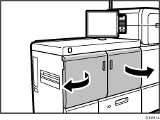
![]() Open the left front cover of the main unit.
Open the left front cover of the main unit.
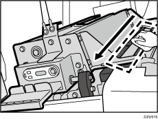
![]() Wipe the glass surface located to the right of the E3 lever in one direction, either from the back to front or from the front to back.
Wipe the glass surface located to the right of the E3 lever in one direction, either from the back to front or from the front to back.
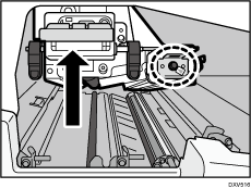
![]() Raise the E3 lever, and then remove the TCRU screw using the TCRU screw driver or a Phillips screwdriver.
Raise the E3 lever, and then remove the TCRU screw using the TCRU screw driver or a Phillips screwdriver.
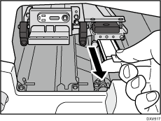
![]() Remove the contact glass by pulling it toward you.
Remove the contact glass by pulling it toward you.
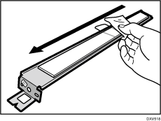
![]() Wipe both sides of the glass in one direction, either from the back to front or from the front to back.
Wipe both sides of the glass in one direction, either from the back to front or from the front to back.
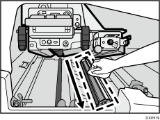
![]() While raising the E3 lever, wipe the roller of the revolver in one direction, either from the back to front or from the front to back.
While raising the E3 lever, wipe the roller of the revolver in one direction, either from the back to front or from the front to back.
Turn the gear on the front side to rotate the roller. Wipe the bias roller and then wipe the shading correction plate while rotating the roller of the revolver.
![]()
The revolver consists of the transport roller, bias roller, and shading correction plate. The shading correction plate is a white curved surface located between the black bias rollers.
![]() After cleaning the roller of the revolver, attach the contact glass that was removed, and fasten the TCRU screw.
After cleaning the roller of the revolver, attach the contact glass that was removed, and fasten the TCRU screw.
![]() Close all covers that were opened.
Close all covers that were opened.
