This section describes how to connect an Ethernet interface cable to the Ethernet port of the USB Device Server.
USB Device Server Option is an interface board for adding an extra Ethernet port. If you install USB Device Server Option, you can connect two Ethernet cables simultaneously: one to the machine's Ethernet port and one to the Ethernet port of USB Device Server Option. An IP address can be assigned to each connection, and you can use one machine to print from different network segments.
![]()
|
![]()
If the main power switch is on, turn it off.
Use the following Ethernet cables.
When using 100BASE-TX/10BASE-T:
Unshielded Twisted Pair Cable (UTP) or Shielded Twisted Pair Cable (STP) and Category type 5 or more
![]() Make sure the main power switch is turned off.
Make sure the main power switch is turned off.
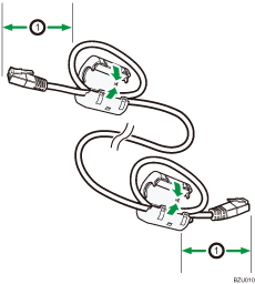
![]() Make a loop at a distance of a few centimeters (1) from each end of the Ethernet interface cable, and then attach to each loop the ferrite core provided with the USB Device Server Option.
Make a loop at a distance of a few centimeters (1) from each end of the Ethernet interface cable, and then attach to each loop the ferrite core provided with the USB Device Server Option.

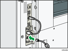
![]() Connect the Ethernet interface cable to the Ethernet port of the USB Device Server Option.
Connect the Ethernet interface cable to the Ethernet port of the USB Device Server Option.
You can use either a straight or crossover Ethernet cable for connecting to the USB Device Server Option.

![]() Connect the other end of the Ethernet interface cable to a network connection device such as a hub.
Connect the other end of the Ethernet interface cable to a network connection device such as a hub.
It may take several seconds for the machine to recognize the USB Device Server Option. If you have disconnected the USB cable, connect the USB cable again.
![]() Turn on the main power switch of the machine.
Turn on the main power switch of the machine.

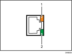
Indicator (orange)
When 100BASE-TX is operating, the LED is lit orange.
Indicator (green)
When 10BASE-T is operating, the LED is lit green.
![]()
Remove the cover of USB2.0 port on the printer and connect the port to the USB port of the USB device server.
When Energy Saver mode is enabled, the LEDs may not light up.
For details about how to turn on the main power switch, see Turning On/Off the Power.
For details about installing the printer driver, see "Installing the Printer Driver", Driver Installation Guide.
