


  |  | ||
![]()
Before beginning work, ground yourself by touching something metal to discharge any static electricity. Static electricity can damage the board.
Do not subject the board to physical shocks.
When installing the SDRAM module, hard disk, and wireless LAN interface board together, install them in the following order: SDRAM module, hard disk, wireless LAN interface board. If the wireless LAN interface board is already installed, remove it before installing the hard disk.
Check the contents of the package.
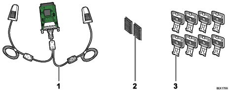
Wireless LAN Interface Board
Two Hook-and-loop Fasteners
Eight Hooks
Turn the printer off and unplug the power cord.
Loosen the two screws and remove the slot cover.
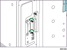
The removed cover will not be reused.
Fully insert the interface board.
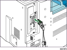
Confirm that the interface board is firmly connected to the controller board.
Tighten the two screws to secure the interface board.
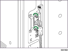
Remove protective paper from the hook-and-loop fasteners, and then place them as far away from each other as possible on the upper side of the printer rear.
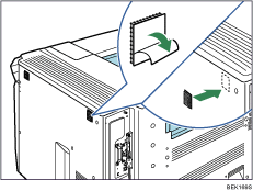
Make sure that the hook-and-loop fasteners are not placed over any screw holes or seams on the printer body.
Remove protective paper from antennas, and then attach the antennas upright to the hook-and-loop fasteners. Attach the antenna coming from a black ferrite core on the right side of the printer rear.
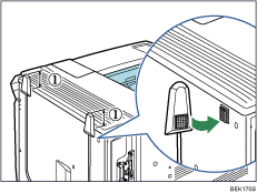
![]() : The antenna tops must project at least 4 cm (1.6inches) above the printer body.
: The antenna tops must project at least 4 cm (1.6inches) above the printer body.
Remove protective paper from four hooks, and then attach the hooks evenly above the concave area on the printer rear.
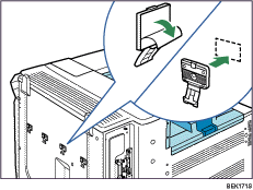
Extra hooks are spare accessories.
Secure the cables using the four hooks. Loop the cable for the antenna on the right as shown.
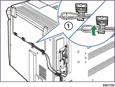
![]() : The loop must have a diameter of at least 1 cm (0.4inches).
: The loop must have a diameter of at least 1 cm (0.4inches).
Plug in the power cord, and then turn on the printer.
Print the configuration page to confirm that the board was attached correctly.
![]()
Confirm that the board was correctly installed by printing the configuration page. If it is correctly installed, "Wireless LAN" will appear for "Device Connection" on the configuration page.
If the board was not installed properly, repeat the procedure from step 2. If it cannot be installed correctly even after reattempting installation, contact your sales or service representative.
For information on printing the configuration page, see "Test Printing", Quick Installation Guide.
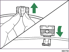
If you need to open the hook, hold the tab of the hook, raise it slightly upward, and then pull it open.
Before using the board, you must configure settings from the printer control panel. For details, see "Wireless LAN Configuration".