

  |  | ||
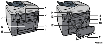
This is a rear view of the machine.

Duplex unit cover button
Press to open the duplex unit cover.
Connector cover
Open this cover to connect a telephone line, extension telephone, USB cable, and to install the network interface board. (The GX 3050SFN model is fitted with a network interface board.)
Duplex unit locks
Use to lock or unlock the duplex unit when attaching or detaching it.
Power cord
Plug the power cord into a wall outlet.
![]() : Plug one end of the power cord into the machine's power inlet and the other end into a wall socket.
: Plug one end of the power cord into the machine's power inlet and the other end into a wall socket.
Connect the grounding wire attached to the power plug directly to a grounding terminal.
Ink collector unit cover
Open this cover to replace the ink collector unit.
Duplex unit cover
Open to remove paper jammed inside the duplex unit.
USB slot
Connect the USB cable from the computer here.
Ethernet Port
If the optional network interface board is installed, connect the Ethernet cable to this (The GX 3050SFN model is fitted with a network interface board.).
Vent
Air is vented here to prevent the inside of the machine from getting too warm. Do not lean anything against the vent or block it in any way. If the inside of the machine gets too warm, a breakdown could occur.
Paper feed wheel
Use to wind out paper jammed around the guide board.
Duplex unit
Turns the paper over when performing duplex printing.
Guide board
Open to remove paper jammed inside the machine.
G3 (analog) line interface connector
Connect a telephone line.
External telephone connector
Connect an extension telephone.