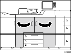
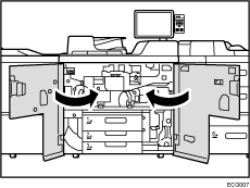
![]() Open the front covers.
Open the front covers.
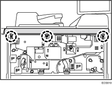
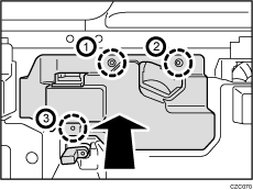
![]() Remove the 3 screws.
Remove the 3 screws.
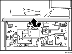
![]() Remove the cover.
Remove the cover.
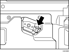
![]() Push the lock lever.
Push the lock lever.
![]() Pulling the lock lever down, pull out the charger unit.
Pulling the lock lever down, pull out the charger unit.
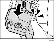
![]() Holding the lock lever and the outer metal frame of the charger unit, pull out the charger unit. Be careful not to touch the center metal portion of the unit.
Holding the lock lever and the outer metal frame of the charger unit, pull out the charger unit. Be careful not to touch the center metal portion of the unit.
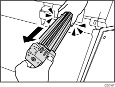
![]() Pull down the lever.
Pull down the lever.
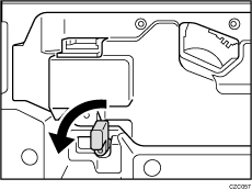
![]() Remove the 3 screws, and then remove the cover.
Remove the 3 screws, and then remove the cover.
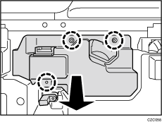
![]() Loosen the drawer stop knob by turning it, and then remove it.
Loosen the drawer stop knob by turning it, and then remove it.
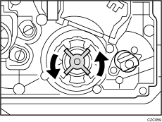
![]() Holding the handle, pull out the development unit drawer.
Holding the handle, pull out the development unit drawer.
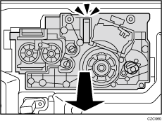
![]() Turn the lock lever.
Turn the lock lever.
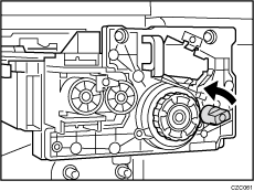
![]() Remove the cleaning unit for photoconductor unit.
Remove the cleaning unit for photoconductor unit.
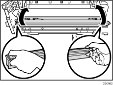
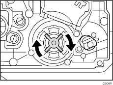
![]() Turn the drum knob.
Turn the drum knob.
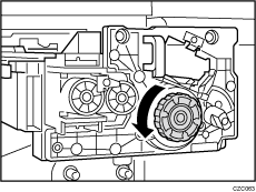
![]() Rotate the handle.
Rotate the handle.
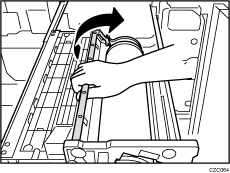
![]() Pull out the photoconductor unit.
Pull out the photoconductor unit.
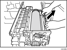
![]() Pat the surface of the photoconductor with a powder puff to apply powder.
Pat the surface of the photoconductor with a powder puff to apply powder.
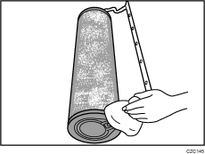
![]() Spread the powder on the photoconductor unit evenly using a dry cloth.
Spread the powder on the photoconductor unit evenly using a dry cloth.
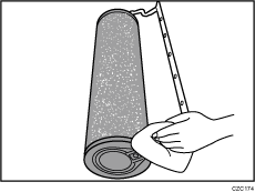
![]() Rotate the photoconductor unit a half-turn until the surface to which the powder has been applied faces down.
Rotate the photoconductor unit a half-turn until the surface to which the powder has been applied faces down.
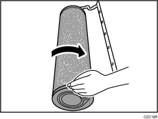
![]() Attach the new photoconductor unit.
Attach the new photoconductor unit.
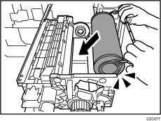
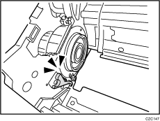
Make sure that the surface to which the powder has been applied does not come into contact with the development roller.
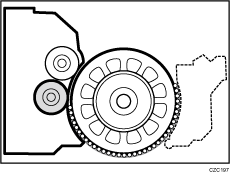
![]() Rotate the handle.
Rotate the handle.
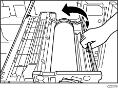
![]() Turn the drum knob while pushing it in to fasten the photoconductor unit.
Turn the drum knob while pushing it in to fasten the photoconductor unit.
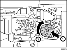
![]() Check that the drum knob is locked securely.
Check that the drum knob is locked securely.
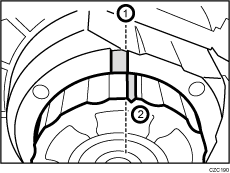
Turn the drum knob until the groove (2) reaches the position to the right of reference position (1).
Unlocked
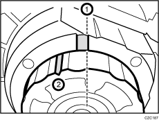
Locked
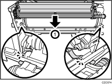
![]() Attach the new cleaning unit for photoconductor unit.
Attach the new cleaning unit for photoconductor unit.
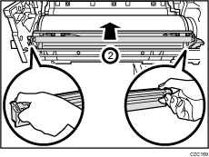
![]() Turn the lock lever, and then secure cleaning unit for photoconductor unit.
Turn the lock lever, and then secure cleaning unit for photoconductor unit.
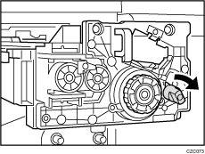
![]() While carefully holding the cleaning unit for photoconductor unit, rotate the photoconductor unit half a turn.
While carefully holding the cleaning unit for photoconductor unit, rotate the photoconductor unit half a turn.
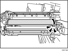
![]() Holding the handle, push the development unit drawer back into the machine.
Holding the handle, push the development unit drawer back into the machine.
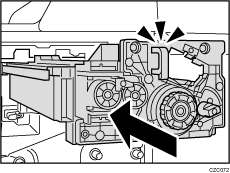
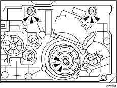
![]() Check that the development unit is attached securely.
Check that the development unit is attached securely.
Detached
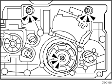
Attached
![]() Install the drawer stop knob, and then fasten it by turning it.
Install the drawer stop knob, and then fasten it by turning it.
![]() Attach the cover, and then secure it with the 3 screws in order.
Attach the cover, and then secure it with the 3 screws in order.
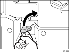
![]() Pull up the lever.
Pull up the lever.
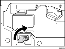
![]()
Push up the lever as shown in the figure. An internal spring will return the lever to its original position. If the lever is held and turned, the roller may not return to the correct position, causing an error.
![]() Engage the new charger unit with the guide rail.
Engage the new charger unit with the guide rail.
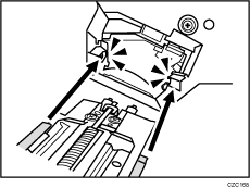
![]() Push the charger unit in horizontally.
Push the charger unit in horizontally.
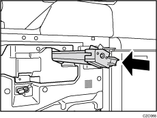
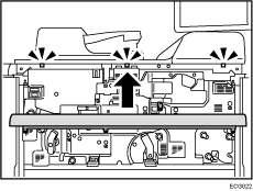
![]() Attach the cover by aligning it with the 3 catches.
Attach the cover by aligning it with the 3 catches.
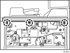
![]() Secure the cover with the 3 screws.
Secure the cover with the 3 screws.
![]() Close the front covers.
Close the front covers.
![]() Reset the counter for replaceable parts.
Reset the counter for replaceable parts.
Do not turn the machine on until you have read how to do so.
