![]()
![]()
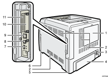
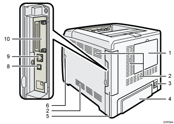
HDD cover
Remove this cover to install the optional hard disk.
Inlet Ventilation Hole
This draws in the air to prevent the temperature inside the printer from rising. Be sure not to block it by placing something against it. Doing so will cause the temperature inside the printer to rise, resulting in a malfunction.
Power connector
Connect the power cord to the printer. Insert the other end into an electrical outlet.
Rear cover
Raise this cover and attach the paper tray cover when loading paper larger than A4 or letter size paper.
Cable cover
Remove this cover to install the optional interface units and the SD card, and to connect various cables.
Front cover open lever
Pull this lever to open the front cover.
USB port A
Connect external devices such as a digital camera, a card authentication device, etc.
USB port B
Use a USB cable to connect the printer to a computer.
Ethernet port
Use a network interface cable to connect the printer to a network.
Optional interface board slot
Optional interface boards can be inserted.
Insert an optional wireless LAN interface board, IEEE 1284 interface board, or USB device server.
Expansion card slots
Remove the cover to install SD cards.