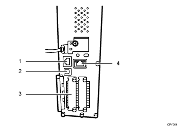
This section explains how to identify the machine's interface and connect the machine according to the network environment.
![]()
|

10BASE-T/100BASE-TX port
Port for connecting a 10BASE-T or 100BASE-TX cable
Use this interface to connect the machine to a network.
USB 2.0 [Type B] port
Port for connecting a USB2.0 [Type B] interface cable
This interface allows the machine to print over USB connection.
Slot A
Install an optional Wireless LAN interface board in this slot.
Wireless LAN interface unit: Required if you want to connect this machine to a wireless LAN. When installed in Slot A, this unit allows you to connect the machine to an IEEE 802.11 a or IEEE 802.11 b/g wireless LAN.
An optional board may be installed in this slot depending on the machine management.
Gigabit Ethernet port (optional)
Port for using a 1000BASE-T, 100BASE-TX, or 10BASE-T cable
Use this interface to connect the machine to a network.
![]()
The Ethernet and Gigabit Ethernet port cannot be used simultaneously. If the optional Gigabit Ethernet board is installed, connect the Ethernet cable to the port on the Gigabit Ethernet board. Communication with the machine will fail if cables are connected to both ports simultaneously.
The USB cable has already been inserted into the machine's USB port. Do not remove this cable. If it is removed, the control panel's SD/USB will no longer be recognized, and the media and data currently being read or written through SD/USB may be damaged.
