![]()
Do not obstruct the ventilation holes by placing objects near or against them. If the printer overheats, a fault might occur.
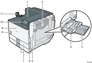
Front and right view

Standard output tray
Printed pages are output here.
Upper right cover
Open this cover to remove jammed paper.
Bypass tray extension
When loading paper larger than A4
 , pull out the bypass tray extension.
Bypass tray
Up to 100 sheets of plain paper can be loaded.
Right cover (Duplex unit)
Open this cover to remove jammed paper, or to replace Maintenance Kit B (the fusing unit and transfer unit).
Handle
Pull out this handle when lifting the printer.
Tray 1, Tray 2
Up to 550 sheets of plain paper can be loaded in each tray.
Power switch
Use this switch to turn the power on and off.
Perform the shutdown procedure before turning the power off. For details about how to shut down the printer, see Turning Off the Power
 .
.Front cover
Open this cover to replace the toner or Maintenance Kit A (the development unit).
Control panel
See Guide to the Names and Functions of the Printer's Control Panel
 .
.Paper support
Extend the paper support when printing on paper larger than A3
 .
.
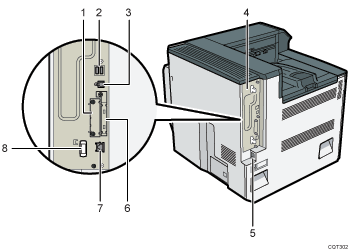
Rear and left view

Optional interface board slot
Optional interface boards can be inserted.
Insert an optional Gigabit Ethernet board, wireless LAN interface board, or IEEE 1284 interface board.
USB port A
Connect external devices to the printer, such as a card authentication device.
USB port B
Use a USB cable to connect the printer to a computer.
Controller board
Slide this out to install the hard disk or SDRAM module.
Power connector
Connect the power cord to the printer. Insert the other end of the cable into an electrical outlet.
Expansion card slots
Remove the cover and install the SD cards.
Ethernet port
Use a network interface cable to connect the printer to a network.
Handle
Hold this handle when pulling out the controller board.
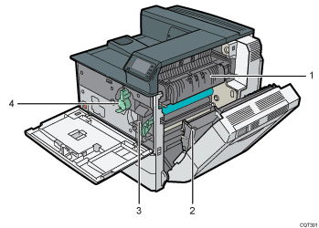
Interior

Fusing unit
Replace the fusing unit when the following message appears:
“Replacement of Maintenance Kit B is now necessary. Replace Maintenance Kit B.”
The fusing unit is included in Maintenance Kit B.
Transfer unit
Replace the transfer unit when the following message appears:
“Replacement of Maintenance Kit B is now necessary. Replace Maintenance Kit B.”
The transfer unit is included in Maintenance Kit B.
Development unit
Replace the development unit when the following message appears:
“Replacement of Maintenance Kit A is now necessary. Replace Maintenance Kit A.”
The development unit is included in Maintenance Kit A.
Toner
Replace the toner when the following message appears:
“
 No toner. Replace Toner Cartridge.”
