Exterior Components
This section describes the names and functions of the exterior components.
![]()
Do not obstruct the ventilation holes by placing objects near them or leaning things against them. If the machine overheats, a fault might occur.
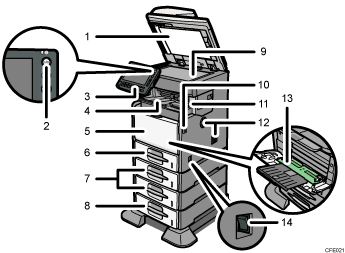
Front and right view

ADF
Lower the ADF over originals placed on the exposure glass.
If you load a stack of originals in the ADF, the ADF will automatically feed the originals one by one. This ADF can be used for two-sided originals.
Operation switch
Press to turn the power on (the operation switch indicator lights up). To turn the power off, press again (the operation switch indicator goes off). See “Turning On/Off the Power”.
Control panel
See “Control Panel”.
Internal tray 1 (types 1 and 2 only)/ Finisher shift tray (type 3 only)
(The illustration shows the finisher shift tray.)
Copied/printed paper and fax messages are delivered here.
Pull out the extender when printing on A4 or 81/2 × 11 size paper or larger.
Front cover
Open to access the inside of the machine. To open this cover, push the front cover release button.
Tray 1
Load paper here print side down.
Paper feed unit (optional)
Load paper here print side down.
Paper feed unit with the casters (optional)
Load paper here print side down.
Exposure glass
Place originals face down here.
Front cover release button
Push this button to open the front cover.
Internal tray 2 (type 2 only)/ finisher (type 3 only)
(The illustration shows the finisher.)
If you select internal tray 2 as the output tray, copied/printed paper and fax messages are delivered here. Pull out the extender on internal tray 2 when printing on A4 or 81/2 × 11 size paper or larger.
The finisher sorts, stacks, and staples multiple sheets of paper.
Ventilation holes
Prevent the machine from overheating.
Bypass tray
Use to print onto plain paper, thick paper, OHP transparencies, label paper (adhesive labels), and custom size paper. Pull out the extender when loading A4 or 81/2 × 11 size paper or larger in the bypass tray.
Main power switch
If the machine does not operate after turning on the operation switch, check if the main power switch is turned on. If it is off, turn it on. See “Turning On/Off the Power”.
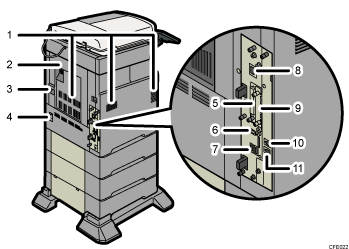
Rear and left view

Ventilation holes
Prevent the machine from overheating.
Rear cover
Open this cover to remove misfed paper.
Rear cover lever
Pull up on this lever to open the rear cover.
Power connector
Connect the power cord to the machine here. Insert the other end of the cable into a nearby wall outlet.
SD card slots
There are two SD card slots. Install SD cards here.
USB 2.0 [Type B] port
Connect the USB2.0 [Type B] interface cable here.
USB Host Interface
Connect the USB interface cable here.
Use this interface to connect the machine to a card authentication device.
10BASE-T/100BASE-TX port
Connect the 10BASE-T or 100BASE-TX cable here.
Optional board slot
Install an optional board in this slot.
External telephone connector (Standard for type 2, and optional for types 1 and 3)
Connect an external telephone here.
G3 interface unit connector (Standard for type 2, and optional for types 1 and 3)
Connect a G3 line here.

