Paper Transfer Shock Jitter / Shock Jitter (When the Positions of K and S Toners Have Been Switched)
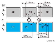
Occurring when entering the paper transfer nip
Occurring when exiting from the paper transfer nip
* Example of occurrence in single-sided printing on A3 size paper at 95PPM
Cause:
Vibration of the intermediate transfer belt due to paper transfer shock jitter occurs, resulting in image transfer fluctuation and one or more horizontal bands.
This occurs on the second and later sheets due to the intermediate transfer belt vibration made when the leading edge of the paper enters the paper transfer nip and when the trailing edge of the paper exits from the paper transfer nip (except for banner sheets).
The problem occurs in various areas, depending on the paper length, print speed (PPM), and color.
This is prone to occur in black-and-white mode and S only mode.
This problem becomes prominent on a single-color "4by4" image.
When the positions of the K and S toners have been switched, this occurs in black-and-white mode. Black toner is positioned in "5st" and farther away from the paper transfer unit than in normal mode, so the effect of vibration of the intermediate transfer belt is more prone to be apparent.
Solutions:
 Check the print job properties when shock jitter occurs.
The color affected with the shock jitter was used for printing 1000 or more sheets of images covering a low image area | Go to the next step. |
Other than the above | Proceed to Step 4. |
 In the [Machine: Maintenance] group on the [Operator Adjust.] menu, execute 0506: [Execute Developer Refreshing] to execute Developer Refreshing for the color with the problem.

Performing this once may not be sufficient to achieve the desired effect. As required, repeat Step 2 up to 5 times.
 Print the image. Has the problem been resolved?
Yes | Finished! |
No | Go to the next step. |
 Check if the positions of the K and S toners have been switched and whether the shock jitter occurred in black-and-white mode.
Yes | Go to the next step. |
No | Proceed to Step 7. |
 Switch the positions of K and S toners. (back to their normal positions)
 Print the image. Has the problem been resolved?
Yes | Finished! |
No | Go to the next step. |
 If the paper is not registered as custom paper, register the brand of the paper.
 In [Detailed settings] for custom paper, select 1237: [Print Speed (Sheet Interval Adj)], and then decrease the values of the following items according to the mode you use.
1237-01: Print Speed (Sheet Interval Adj): BW/FC/FCS: BW/FC/FCS
1237-02: Print Speed (Sheet Interval Adj): FCS: Clear/Special
1237-03: Print Speed (Sheet Interval Adj): FCS: White
1237-04: Print Speed (Sheet Interval Adj): FCS: Metallic
Increase the intervals between the transported sheets so as to move the areas affected by the shock jitter out of the print area or between the sheets.
If the problem is caused by the intermediate transfer belt vibration made when the paper enters the paper transfer nip, you can move the areas affected by the shock jitter approximately 5 mm toward the leading edge of the paper by decreasing the value by 1 %.
If the problem is caused by the intermediate transfer belt vibration made when the paper exits from the paper transfer nip, you can move the areas affected by the shock jitter approximately 10 mm toward the leading edge of the paper by decreasing the value by 1 %.
Depending on the value, throughput may be reduced.
 Print the image. Has the problem been resolved?
Yes | Finished! |
No | Go to the next step. |
 In [Detailed settings] for the custom paper you are using, select 1212: [Image Transfer Output], increase the value by one step.
1212-02: Image Transfer Output: FC/FCS: Black
1212-03: Image Transfer Output: FC/FCS: Cyan
1212-04: Image Transfer Output: FC/FCS: Magenta
1212-05: Image Transfer Output: FC/FCS: Yellow
1212-06: Image Transfer Output: FC/FCS: Clear/Special
1212-07: Image Transfer Output: FC/FCS: White
1212-08: Image Transfer Output: FC/FCS: Metallic
Increasing the value may increase the density. As required, execute process Setting and calibration.
The page yield becomes affected.
Photoconductor-related ghosting may occur.
Small-pitch banding may worsen.
 In [Detailed settings] for the custom paper you are using, select 1231: [Print Speed], and then decrease the value in the following corresponding settings by one level.
Productivity Priority
1231-01: Print Speed: BW/FC/FCS: BW/FC/FCS
1231-02: Print Speed: FCS: Clear/Special
1231-03: Print Speed: FCS: White
1231-04: Print Speed: FCS: Metallic
1231-06: Print Speed: S: Clear/Special
1231-07: Print Speed: S: White
1231-08: Print Speed: S: Metallic
High Quality
1231-10: Print Speed: BW/FC/FCS: Fuser Setting HQ: BW/FC/FCS
1231-11: Print Speed: FCS: Fuser Setting HQ: Clear/Special
1231-12: Print Speed: FCS: Fuser Setting HQ: White
1231-13: Print Speed: FCS: Fuser Setting HQ: Metallic
1231-15: Print Speed: S: Fuser Setting HQ: Clear/Special
1231-16: Print Speed: S: Fuser Setting HQ: White
1231-17: Print Speed: S: Fuser Setting HQ: Metallic
For example, if the print speed is [High], decrease it to [Middle], and if decreasing the speed to [Middle] does not have a sufficient effect, decrease the speed to [Low].
If it is already set to [Low], there is no other solution.
 Print the image. Has the problem been resolved?
Yes | Finished! |
No | If presently set to [Middle], lower it to [Low], and then print again to see if there is any improvement. If the problem persists even after decreasing the value to "Low", there is no other solution. |
Select "Clear/Special" when using Neon Yellow, Neon Pink, or Invisible Red. Select "Metallic" when using Gold or Silver.
After performing the solution, it is recommended to perform the color calibration of the external printer controller.