![]()
|
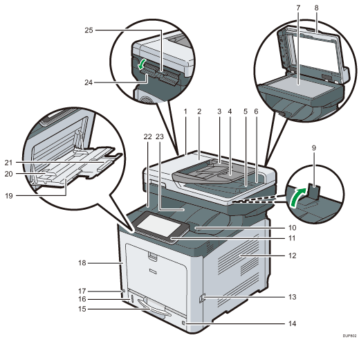
Exterior: Front view

ADF
Lower the ADF over originals placed on the exposure glass.
If you load a stack of originals in the ADF, the ADF will automatically feed the originals one by one.
ADF cover
Open this cover to remove originals jammed in the ADF.
Input tray for the ADF
Place stacks of originals here.
Extender for the ADF tray
Extend this when placing paper longer than A4 in the input tray for ADF.
Stop fence for the ADF
Pull out this fence to prevent originals from falling off.
Output tray for the ADF
Originals scanned with the ADF are output here.
Exposure glass
Place originals face down here.
Cover for the exposure glass
Open this cover to place originals on the exposure glass.
Stop fence
Raise the rear fence to prevent A4 or letter-size prints from falling behind the machine.
After using the stop fence, be sure to return it to its original position. The fence may be damaged if it is hit with something or excessive force is applied.
Top cover open lever
Pull this lever upward to open the top cover.
Control panel
See Guide to the Names and Functions of the Machine's Control Panel.
Ventilation holes
Prevent overheating.
Front cover open lever
Pull this lever to open the front cover.
Paper size dial
Use this dial to specify the paper size. To use a paper size that is not indicated on the paper size dial, set the dial to "
 ". If this is the case, set the paper size using the control panel.
Paper tray (Tray 1)
Load paper here.
Remaining paper indicator
Indicates the approximate amount of paper remaining in the tray.
Main power switch
To operate the machine, the main power switch must be on. If it is off, turn the switch on.
Front cover
Open this cover when replacing the waste toner bottle, etc., or removing jammed paper. Pull the right side lever to open the front cover.
Bypass tray
Use to copy or print on thick paper, envelopes, and label paper (adhesive labels).
Paper guides
When loading paper in the bypass tray, align the paper guides flush against the paper.
Extender for the bypass tray
Pull this extender out when loading A4
 , 81/2 × 11
 or larger size paper in the bypass tray.
Top cover
Open this cover to replace the toner or black drum unit/color drum units.
Standard tray
Output is stacked here with the print side down.
ID Card Feeder cover
Open this cover to set a larger size card or paper in the ID Card Feeder.
ID Card Feeder
Use this to copy or scan both sides of a card such as an ID card. Load one original at a time.
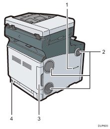
Exterior: Rear view

Handset slit
 (mainly North America)
Attach the handset bracket to the slit.
Ventilation holes
Prevent overheating.
Cable cover
Remove this cover to connect an Ethernet, USB cable, telephone line, or external telephone.
Power connector
Connect the power cord to the machine. Insert the other end into an electrical outlet.
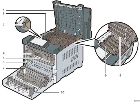
Interior: Front view

Toner
Loads from the machine rear, in the order of black (K), cyan (C), magenta (M), and yellow (Y).
Messages appear on the screen when the toner cartridge needs to be replaced, or a new cartridge needs to be prepared. For details about the messages that appear on the screen when consumables need to be replaced, see Replenishing and Replacing Consumables.
Inner cover
Open this cover when replacing the black drum unit/color drum units.
Inner cover open lever
Pull this lever to open the inner cover.
Fusing unit
Messages appear on the screen when the fusing unit needs to be replaced, or a new fusing unit needs to be prepared. For details about the messages that appear on the screen when consumables need to be replaced, see Replenishing and Replacing Consumables.
Intermediate transfer unit
Messages appear on the screen when the intermediate transfer unit needs to be replaced, or a new intermediate transfer unit needs to be prepared.
For details about the messages that appear on the screen when consumables need to be replaced, see Replenishing and Replacing Consumables.
Waste toner bottle
Collects toner that is wasted during printing. Messages appear on the screen when the waste toner bottle needs to be replaced, or a new waste toner bottle needs to be prepared. For details about the messages that appear on the screen when consumables need to be replaced, see Replenishing and Replacing Consumables.
Transfer roller
If the message appears on the control panel, replace the transfer roller, which is included with the intermediate transfer unit.
For details about the messages that appear on the screen when consumables need to be replaced, see Replenishing and Replacing Consumables.
Replace the transfer roller and the intermediate transfer unit together.
LED heads
Clean the LED heads if black or color lines appear on prints.
Black drum unit / Color drum units
The drum units are installed in the order of black (K), cyan (C), magenta (M), and yellow (Y).
Messages appear on the screen when the drum unit needs to be replaced, or a new drum unit needs to be prepared.
For details about the messages that appear on the screen when consumables need to be replaced, see Replenishing and Replacing Consumables.
knob
If you cannot pull out jammed paper, remove it by turning the knob.
