![]()
This solution only works when the thickness of the paper is equivalent to Paper Weight 4 or higher. Do not try this as a solution when using paper with a thickness equivalent to Paper Weight 3 or lower, as it may cause paper misfeeding.
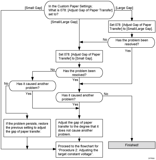
Carry out the following sequence of procedures. Terminate the sequence as soon as the problem is resolved.
Procedure 1: Adjusting the gap of paper transfer

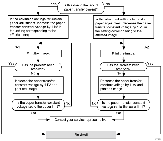
Procedure 2: Adjusting the target constant voltage

Print Mode |
Settings to adjust |
|---|---|
Printing in black and white |
064: [Ppr Trnsf Cnstnt Voltage: B&W: Side 1] |
065: [Ppr Trnsf Cnstnt Voltage: B&W: Side 2] |
|
Full color printing or full color + special color |
070: [Ppr Trnsf Constant Voltage: FC: Side 1] |
071: [Ppr Trnsf Constant Voltage: FC: Side 2] |
|
Printing in special color only |
076: [Ppr Trnsf Constant Voltage: S: Side 1] |
077: [Ppr Trnsf Constant Voltage: S: Side 2] |
If the white spots at the leading edge become worse, execute the other workflow in steps of 0.5 kV. If S1 workflow worsens the problem, execute the S2 workflow.
![]()
Special color mode is available for Pro C7100X, Pro C7110X, Pro C7100SX, and Pro C7110SX.
After performing the solution, it is recommended to perform the color calibration of the external controller.
Depending on the problem, adjust the value in 031: [Paper Transfer Current; Lead Edge: B&W] for black and white printing and 039: [Paper Transfer Current; Lead Edge: FC] for full-color printing.
