Head Position
Adjusts the print head. Perform this operation if printed lines are vertically misaligned or printed colors are blurred.
To check adjustment values, print test patterns applying "High Speed", "Standard", "High Quality", "Envelope Print" settings.
If there are several lines in the test pattern, check adjustment values for each line, and adjust the print head positions. If the adjustment value is set to "0", adjustment is not necessary. Adjust all lines so their adjustment values indicate "0".
![]() Press the [
Press the [![]() /Menu] key.
/Menu] key.
![]() Press the [
Press the [![]() ] or [
] or [![]() /Menu] key to display [Maintenance], and then press the [#Enter] key.
/Menu] key to display [Maintenance], and then press the [#Enter] key.
| Menu: Maintenance |
![]() Press the [
Press the [![]() ] or [
] or [![]() /Menu] key to display [Head Position], and then press the [#Enter] key.
/Menu] key to display [Head Position], and then press the [#Enter] key.
| Maintenance: Head Position |
![]() Press the [
Press the [![]() ] or [
] or [![]() /Menu] key to display [Pr.Test Pattern], and then press the [#Enter] key.
/Menu] key to display [Pr.Test Pattern], and then press the [#Enter] key.
| Head Position: Pr.Test Pattern |
![]() Press the [
Press the [![]() ] or [
] or [![]() /Menu] key to select the target's resolutions, and then press the [# Enter] key.
/Menu] key to select the target's resolutions, and then press the [# Enter] key.
| Pr.Test Pattern: High Speed |
A test pattern to adjust print head positions is printed.
![]() To determine the adjustment value, select the square that is faintest (closest to white). Alternatively, select the square whose internal lines overlap to form a single color.
To determine the adjustment value, select the square that is faintest (closest to white). Alternatively, select the square whose internal lines overlap to form a single color.
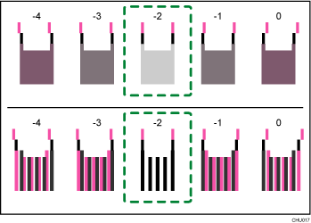
Combined two-color lines form squares, and depending on line overlapping, (white) spaces between the lines are painted and look darker. Sometimes the colors of the lines are identical.
For this illustration, the adjustment value is "-2". Checking adjustment values for each item is required.
If you cannot determine the adjustment value, select the square that is between the straightest lines.
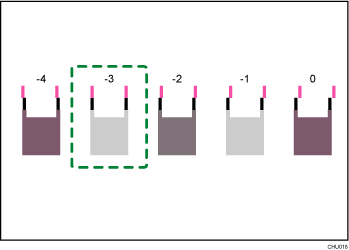
Each vertical line is made of an upper part and lower part. If the print head is not properly positioned, the vertical line will be displayed as two disconnected lines, so that the line looks misaligned.
If you still cannot determine the adjustment value, locate the square that is between adjacent squares whose lines form symmetry. Adjacent squares can be one or two places either side (at positions ±1 or ±2).
This illustration indicates an adjustment value that is set to "-1".
![]() Press the [
Press the [![]() ] or [
] or [![]() /Menu] key to display [Adjustment], and then press the [#Enter] key.
/Menu] key to display [Adjustment], and then press the [#Enter] key.
| Head Position: Adjustment |
![]() Press the [
Press the [![]() ] or [
] or [![]() /Menu] key to select a resolution from Step 5, and then press the [#Enter] key.
/Menu] key to select a resolution from Step 5, and then press the [#Enter] key.
| Adjustment: High Speed |
![]() Select the items that you need to adjust, and then press the [# Enter] key.
Select the items that you need to adjust, and then press the [# Enter] key.
| Adjustment: 1.A |
![]() Enter the optimal adjustment values from Step 6, and then press the [#Enter] key.
Enter the optimal adjustment values from Step 6, and then press the [#Enter] key.
| A: (-4, +4) 0 |
![]() Press the [Escape] key.
Press the [Escape] key.