![]()
Do not obstruct the ventilation holes by placing objects near or against them. If the printer overheats, a malfunction might occur.
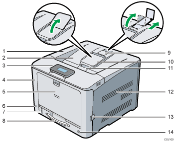
Front view

Top cover
Open this cover to replace the toner or black drum unit/color drum units.
Standard tray
Output is stacked here with the print side down.
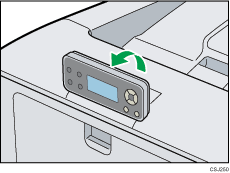
Control panel
You can set the display up with your hands. Adjust the angle of it to see clearly.

For details, see Guide to the Names and Functions of the Printer's Control Panel.
Front cover
Open this cover when replacing the waste toner bottle, etc., or removing jammed paper.
Pull the right side lever to open the front cover.
Bypass tray
Up to 100 sheets of plain paper can be loaded.
For details about the sizes and types of paper that can be used, see Paper Specifications.
Main power switch
Use this switch to turn the power on and off.
Perform the shutdown procedure before turning the power off. For details about how to shut down the printer, see Turning Off the Power.
Remaining paper indicator
Indicates the approximate amount of paper remaining in the tray.
Standard paper feed tray (Tray 1)
Up to 250 sheets of plain paper can be loaded.
For details about the sizes and types of paper that can be used, see Paper Specifications.
Stop fence (A3, Legal, and Double letter-size prints)
Raise the rear fence (by pulling it in the direction of the arrow) to prevent A3, Legal, and Double letter-size prints from falling behind the printer.
After using the stop fence, be sure to return it to its original position. The fence may be damaged if it is hit with something or excessive force is applied.
Standard tray extension
Use this to support sheets that come out curled after they are printed.
Flip open the extension by pushing down on the end that is toward the rear of the printer.
After using the standard tray extension, be sure to return it to its original position. The tray may be damaged if it is hit with something or excessive force is applied.
Top cover open lever
Pull this lever upward to open the top cover.
Vents
To prevent overheating, heat from internal components is released through these vents. Malfunctions and failure can result if these vents are blocked or obstructed.
Front cover open lever
Pull this lever to open the front cover.
Paper size dial
Use this dial to specify the paper size. To use a paper size that is not indicated on the paper size dial, set the dial to "
 ". If this is the case, set the paper size using the control panel.
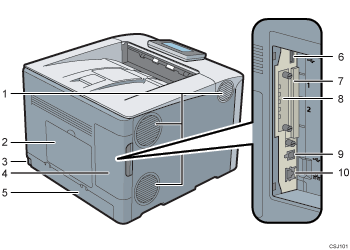
Rear view

Vents
To prevent overheating, heat from internal components is released through these vents. Malfunctions and failure can result if these vents are blocked or obstructed.
Memory cover
Remove this cover to install the optional SDRAM module and hard disk.
Power connector
Connect the power cord to the printer. Insert the other end into an electrical outlet.
Cable cover
Remove this cover to install the optional interface units and the SD card, and to connect various cables.
Rear cover
Raise this cover and attach the paper tray cover when loading paper larger than A4 or letter size paper.
USB port A
Connect external devices such as a digital camera, a card authentication device, etc.
Expansion card slots
Remove the cover to install SD cards.
Optional interface board slot
Optional interface boards can be inserted.
Insert an optional wireless LAN interface board or IEEE 1284 interface board.
USB port B
Use a USB cable to connect the printer to a computer.
Ethernet port
Use a network interface cable to connect the printer to a network.
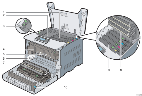
Interior

Toner
Loads from the printer rear, in the order of black (K), cyan (C), magenta (M), and yellow (Y).
If the following message appears on the control panel, replace the toner cartridge:
"
 Out of toner"
"
 Add Toner"
Inner cover
Open this cover when replacing the black drum unit/color drum units.
Inner cover open lever
Pull this lever to open the inner cover.
Fusing unit
If the following message appears on the control panel, replace the fusing unit:
“Replacmnt Rqrd:Fusing Unit”
Intermediate transfer unit
If the following message appears on the control panel, replace the intermediate transfer unit:
“Replacemnt Requird:IntTrans”
Waste toner bottle
Collects toner that is wasted during printing.
If a message prompting you to replace it appears on the display, replace the waste toner bottle.
"
 Waste Toner Bottle full"
Transfer roller
If the following message appears on the control panel, replace the transfer roller, which is included with the intermediate transfer unit:
“Replacemnt Requird:IntTrans”
Replace the transfer roller and the intermediate transfer unit together.
LED heads
Clean the LED heads if black or color lines appear on prints.
Black drum unit / Color drum units
The drum units are installed in the order of black (K), cyan (C), magenta (M), and yellow (Y). Replace the relevant black drum unit/color drum units when the following message appears:
“Replacmnt Requird:PCU:Black”
“Replacmnt Requird:PCU:Color”
knob
If you cannot pull out jammed paper, remove it by turning the knob.
