
| |||
This section explains names and functions of the parts on the rear side of the printer.
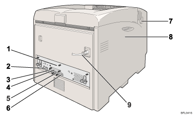
Controller Board
Slide this out to install options such as the memory unit or printer hard disk. Plug cables such as the USB cable and Ethernet cable into their connectors.
Ethernet Port
Use a network interface cable to connect the printer to the network.
USB Port
Use a USB cable to connect the printer to a computer.
Optional Interface Board Slot
Insert an optional Wireless LAN interface unit, Bluetooth interface unit, Gigabit Ethernet board, or 1284 interface board in this slot.
SD Card Slots
Install SD cards in these slots. There are two slots.
When you use the SD card, use the right slot.
USB Host Port
Use a USB cable to connect the printer to the digital camera.
Front Cover (A) Open Levers
Left Cover
Open this cover when replacing the photo conductor unit (PCU), intermediate transfer unit or waste toner bottle.
Power Cable
![]() The power cable is separated. Connect the power cable to the printer.
The power cable is separated. Connect the power cable to the printer.
![]() The power cable is fixed to the back side.
The power cable is fixed to the back side.
| Copyright (C) 2007 |